House electrical control and alarmsHouse electrical control and alarms
Power circuits, local control, alarms and manual operation connect feeding, water, egg, manure and climate equipment. Interfaces are documented before wiring and commissioning.
Power circuits, local control, alarms and manual operation connect feeding, water, egg, manure and climate equipment. Interfaces are documented before wiring and commissioning.
01
Circuit separation
Major mechanical systems are grouped for fault isolation and service.
02
Manual recovery
Manual start/stop and safe fallback procedures are defined for power or communication faults.
03
Commissioning
Alarm, interlock, sensor and local operation are tested with mechanical equipment on site.
02 / Equipment details
See each equipment detail in context.
Each catalogue image explains a visible structure or process; pictured configurations are not a fixed supply list.
Product catalogue visual / 01
01 / Equipment details
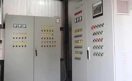
Cabinet fronts and circuit groups
The source shows multiple cabinet fronts. Feed, manure, egg and climate circuits should be grouped in the electrical schedule; cabinet appearance does not establish circuit capacity.
Configure for your site:Confirm motor loads, circuit count and cabinet location.
Product catalogue visual / 02
02 / Equipment details
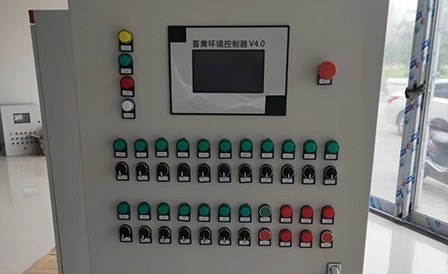
Local operating interface
The panel close-up shows start/stop controls and a display area. Local manual mode, permissions and alarm acknowledgement need to be specified alongside automation.
Configure for your site:List local starts, interlocks, alarms and manual recovery.
Product catalogue visual / 03
03 / Equipment details
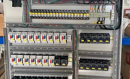
Protection and wiring inside cabinet
The source shows protective devices, terminal rows and wiring. Brands, quantities and wiring follow final electrical drawings; the image illustrates grouping and service access.
Configure for your site:Confirm drawings, wire labels, protection settings and spare capacity.
03 / System connections
How the equipment connects.
Functional connection map · not a construction drawing
01
Equipment signals and power
Enter from the confirmed mechanical schedule.
→
02
Control and protection
Operate grouped circuits and record alarms.
→
03
Local operation and recovery
Retain human checks and fallback procedures.
06 / Configuration scope
Turn a product family into a project specification.
Final model and supply scope are set in a written project specification.