Manure drying and treatment interfaceManure drying and treatment interface
A downstream option for projects that need to reduce moisture before storage or further processing. Its airflow, feed rate and unloading route follow the actual manure quantity and moisture.
A downstream option for projects that need to reduce moisture before storage or further processing. Its airflow, feed rate and unloading route follow the actual manure quantity and moisture.
01
Incoming material
Manure volume, belt schedule and moisture decide inlet size and buffer capacity.
02
Airflow and tiers
Drying surfaces and ventilation loads are calculated with local climate and exhaust treatment.
03
Outlet
The end transfer must connect to storage, vehicle loading or the next treatment stage.
02 / Equipment details
See each equipment detail in context.
Each catalogue image explains a visible structure or process; pictured configurations are not a fixed supply list.
Product catalogue visual / 01
01 / Equipment details
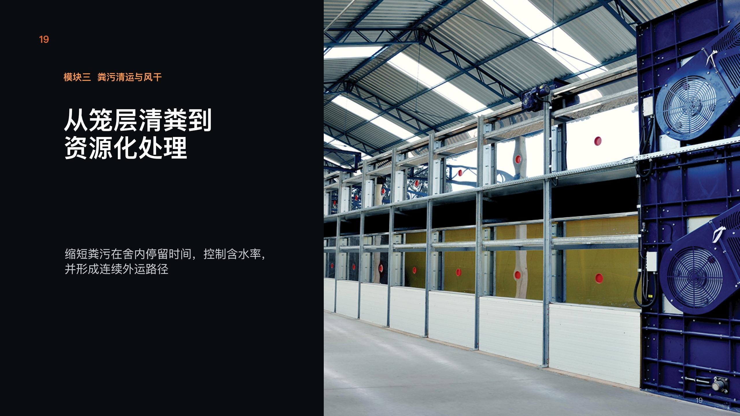
Drying equipment overview
The cover shows multi-tier manure-drying equipment. It is downstream of manure removal and must not be presented as the house ventilation system.
Configure for your site:Define inlet volume, moisture and final destination.
Product catalogue visual / 02
02 / Equipment details
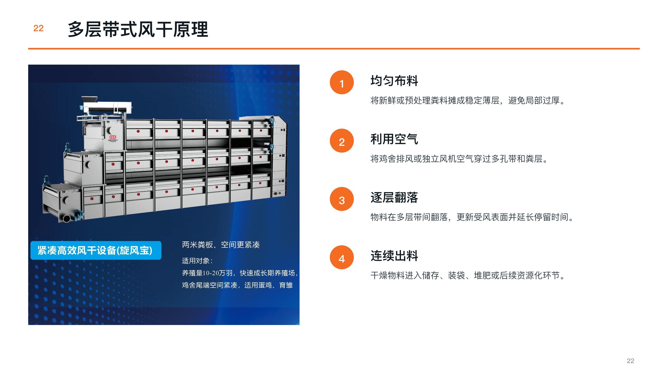
Multi-tier drying principle
The supplied schematic explains material moving across tiers, contacting air and leaving at the outlet. Tier count, airflow and throughput require project confirmation.
Configure for your site:Confirm air supply, inlet, outlet and service points.
Product catalogue visual / 03
03 / Equipment details
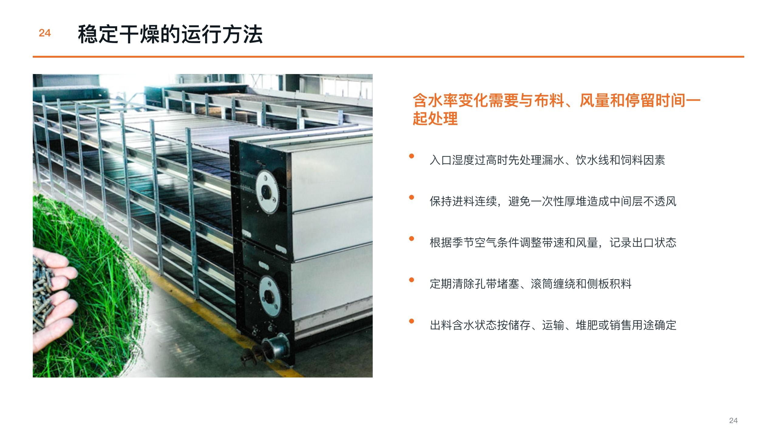
Installed unit and air path
The photograph shows the dryer enclosure and air-handling area. Input moisture, climate and run time affect results; performance cannot be inferred from the image.
Configure for your site:Define ventilation, power, drainage and maintenance conditions.
03 / System connections
How the equipment connects.
Functional connection map · not a construction drawing
01
Manure inlet
Receive a confirmed volume from manure removal.
→
02
Multi-tier drying
Use air and movement to reduce moisture.
→
03
Outlet and transport
Connect to storage or further treatment.
06 / Configuration scope
Turn a product family into a project specification.
Final model and supply scope are set in a written project specification.