Poultry house steel structure and interfacesPoultry house steel structure and interfaces
Structure, enclosure, foundation and equipment are designed as one project. The house span, clear height, roof load, ventilation openings and service corridors determine cage-row feasibility.
Structure, enclosure, foundation and equipment are designed as one project. The house span, clear height, roof load, ventilation openings and service corridors determine cage-row feasibility.
01
Structural loading
Cage, silo, ventilation and local wind/snow loads are reviewed with the civil engineer.
02
Interfaces
Openings, supports, power, water, drainage and maintenance clearances are fixed before fabrication.
03
Build sequence
Delivery lots and installation zones are marked to reduce rehandling on site.
02 / Equipment details
See each equipment detail in context.
Each catalogue image explains a visible structure or process; pictured configurations are not a fixed supply list.
Product catalogue visual / 01
01 / Equipment details
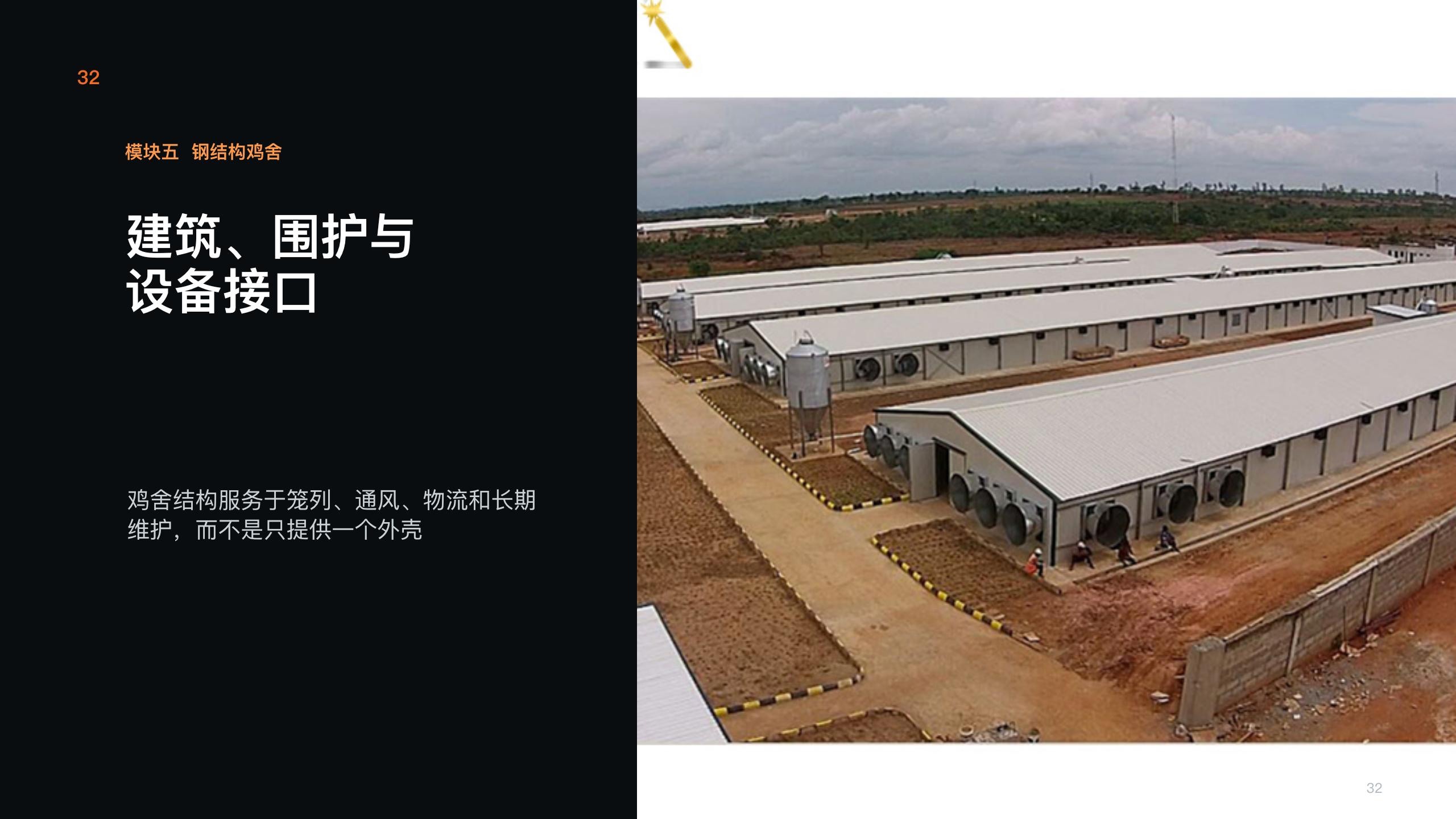
Poultry-house exterior
The source shows multiple poultry houses, roofs and site roads. It is a layout reference; span, structural loads and local code compliance require project engineering.
Configure for your site:Confirm site, foundations, roads and drainage.
Product catalogue visual / 02
02 / Equipment details
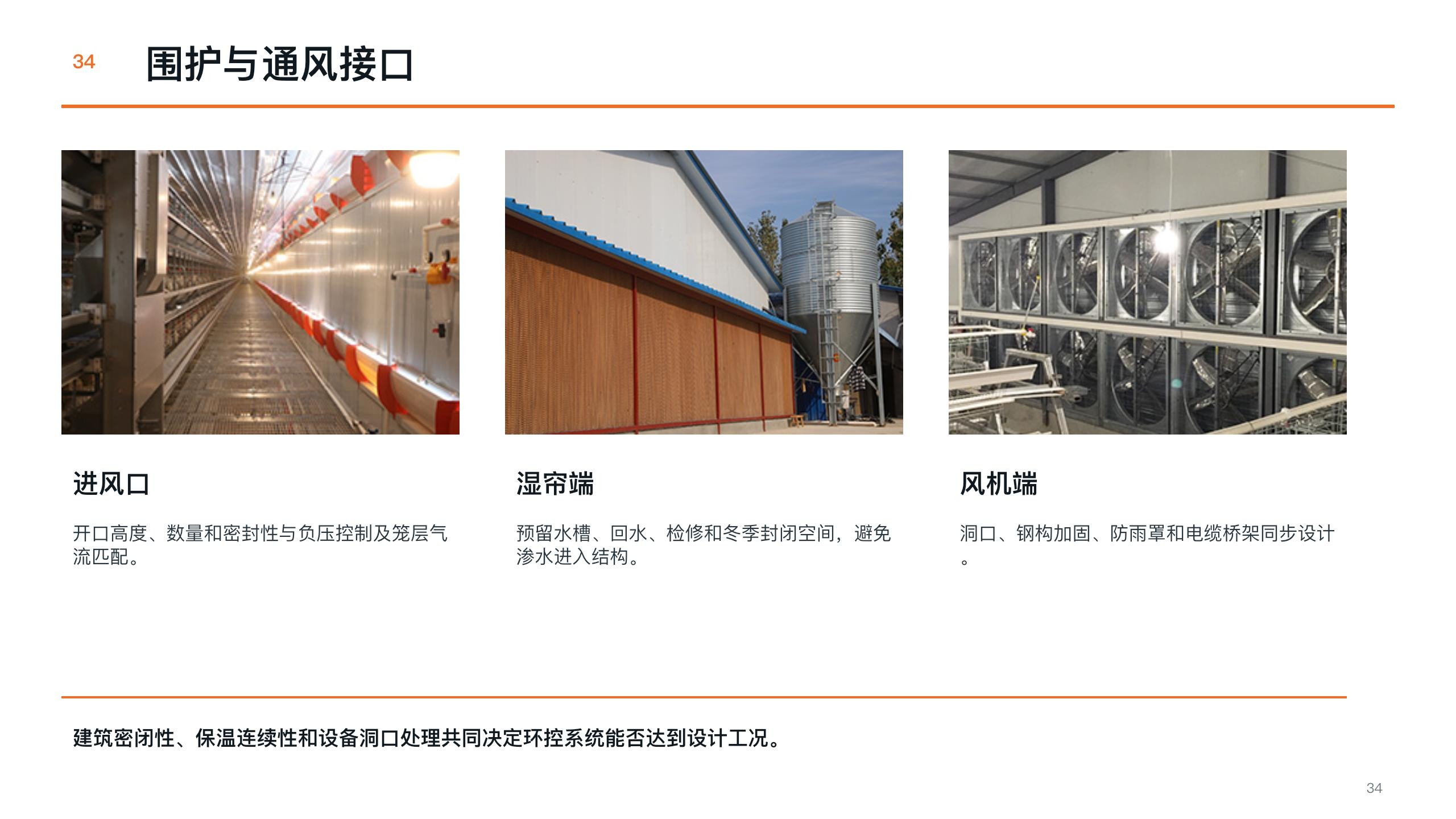
Envelope and ventilation openings
The source compares inlet, wall-envelope and fan-wall examples. Opening dimensions are coordinated with cage layout, ventilation equipment and local climate.
Configure for your site:Mark openings and MEP interfaces on civil drawings.
Product catalogue visual / 03
03 / Equipment details
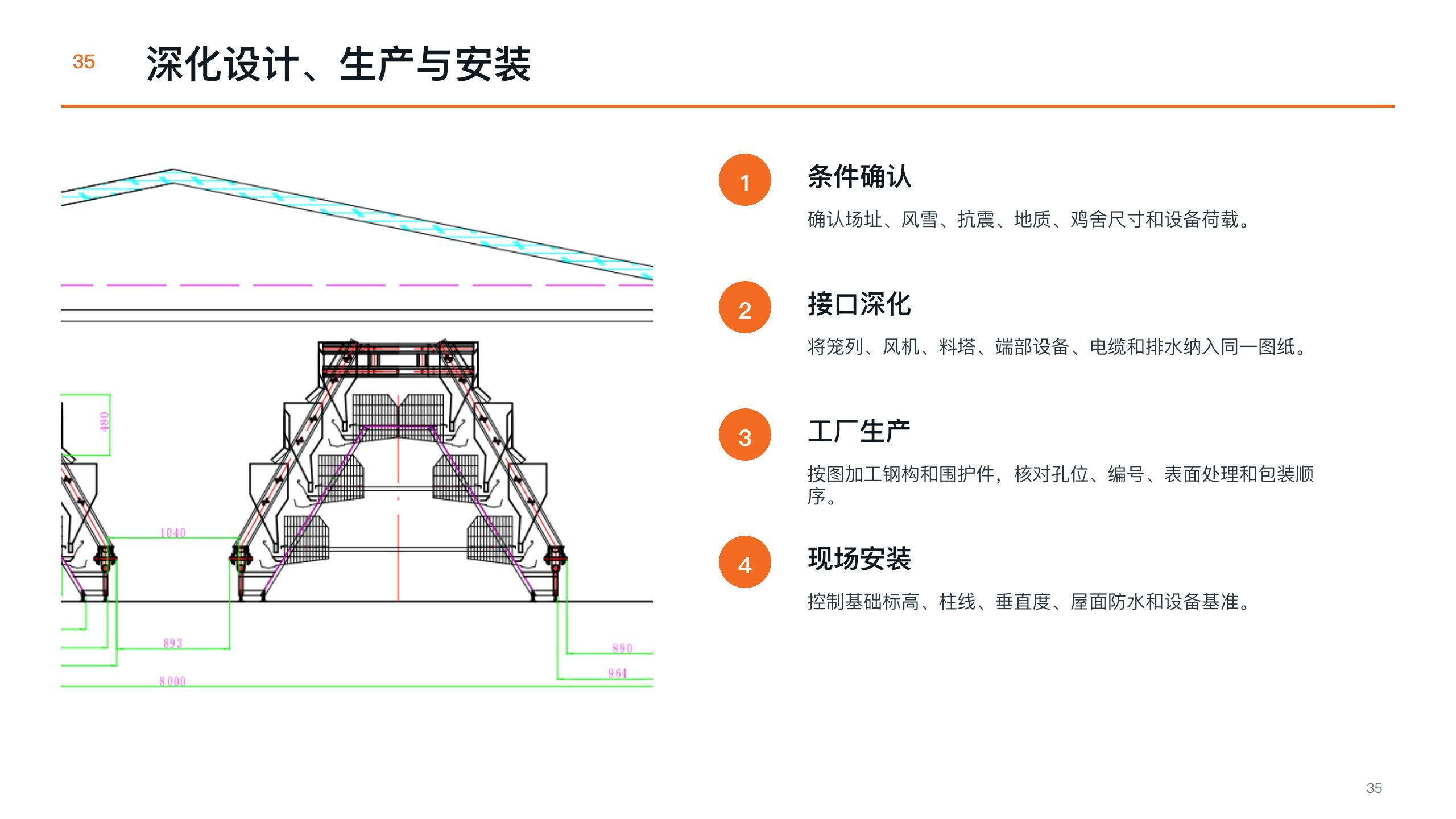
House section and equipment layout
The supplied drawing is a section and equipment-position concept. It helps review clear height, lifting access and aisles; it is not a construction-ready structural drawing.
Configure for your site:Confirm column grid, rows, fans, utilities and installation order.
03 / System connections
How the equipment connects.
Functional connection map · not a construction drawing
01
Site and foundation
Design for loads and drainage.
→
02
Frame and envelope
Reserve spans, clearance and openings.
→
03
Equipment and MEP
Coordinate cages, ventilation and utilities.
06 / Configuration scope
Turn a product family into a project specification.
Final model and supply scope are set in a written project specification.
Information to share
01Local wind/snow loads, seismic and codes
02Span, column grid, eave and clear height
03Ventilation openings, equipment loads and access