A vertically stacked production line that gives each tier its own feeding, drinking, egg collection and manure route. Designed for closed houses where aisle width, headroom and end drives can be planned together.
A vertically stacked production line that gives each tier its own feeding, drinking, egg collection and manure route. Designed for closed houses where aisle width, headroom and end drives can be planned together.
01
Tier-by-tier separation
Feed, water, eggs and manure are kept on defined routes at each tier. This makes the end-of-row interfaces visible during installation and service.
02
Egg path
A sloped cage floor guides eggs to the longitudinal belt; transfer geometry and belt speed must be checked before connecting the central conveyor.
03
Maintenance access
Door openings, aisle width and end-drive clearance are set with the actual house plan, not a stand-alone cage drawing.
02 / Equipment details
See each equipment detail in context.
Each catalogue image explains a visible structure or process; pictured configurations are not a fixed supply list.
Product catalogue visual / 01
01 / Equipment details
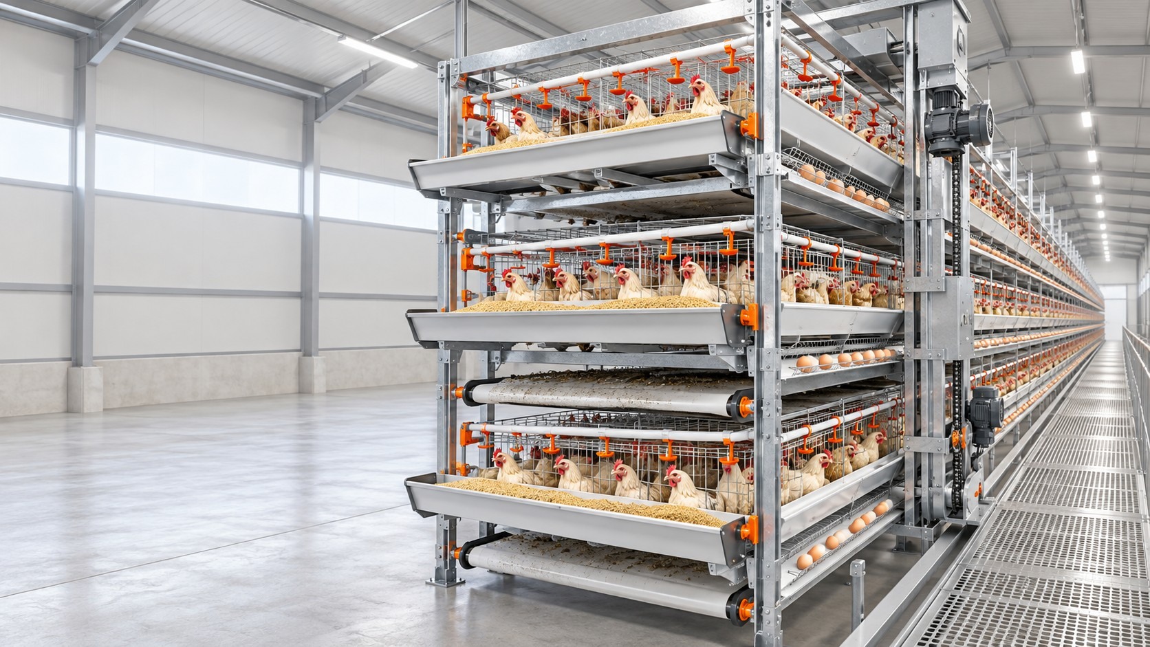
Tiered row arrangement
The supplied overview shows the relative positions of tiered cages, front troughs, lower conveying paths and the service aisle. It is a configuration illustration; tier count and clearances cannot be read as final specifications.
Configure for your site:Confirm tiers, row spacing and end access against the house clear height.
Product catalogue visual / 02
02 / Equipment details
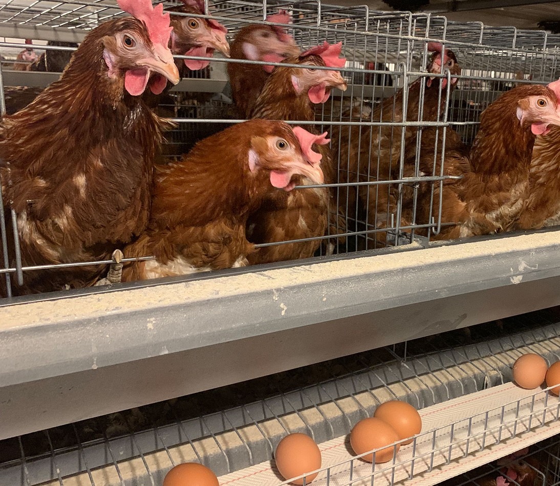
Cage front and egg position
This source image shows the cage front, feed access and eggs at the front edge. It supports a review of bird reach, the egg transition and door access; it does not identify a specified belt model.
Configure for your site:Confirm trough height, front mesh, egg slope and collection interface.
Product catalogue visual / 03
03 / Equipment details
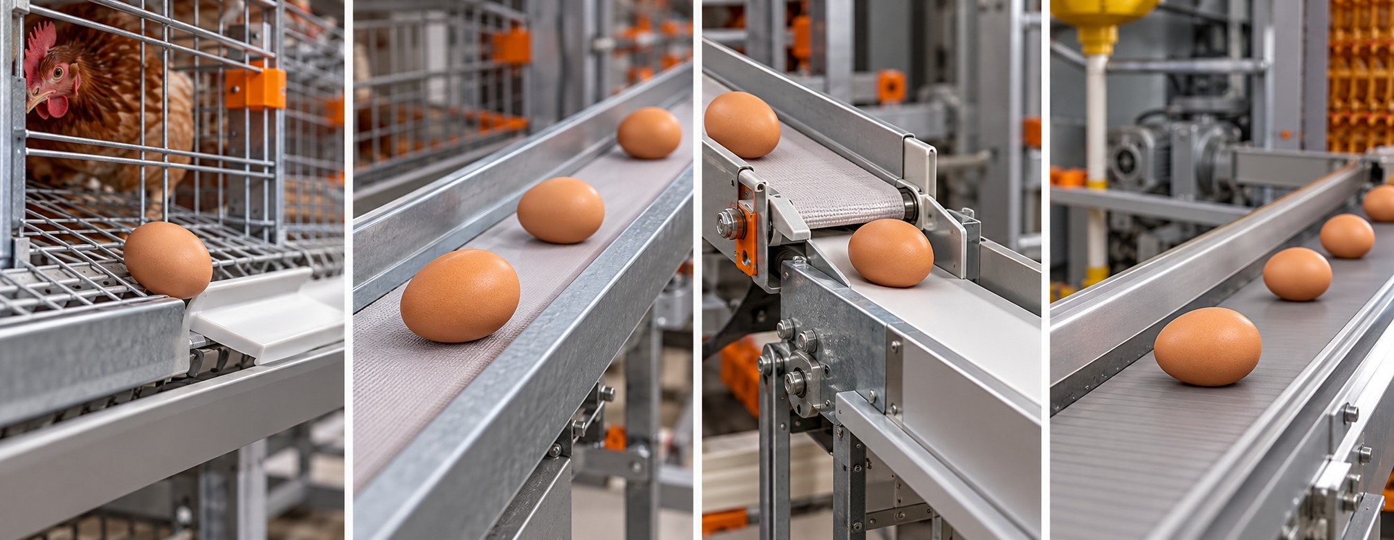
Egg transfer sequence illustration
The supplied illustration places cage exit, longitudinal transfer, handoff and central collection in one sequence. It explains the route; exact mechanical details require confirmation against the selected collection drawings.
Configure for your site:Check belt elevation, handoff drop, end space and egg room direction.
03 / System connections
How the equipment connects.
Functional connection map · not a construction drawing
RouteStartIn-row equipmentHandoffProject check
01Feed inputSilo / main line→Feeding trolley→Tier troughs→Trough position and end drive
02Water inputFilter / regulator→Main water line→Tier nipple lines→Pressure, flushing and drainage
03Egg outputEgg roll-out→Longitudinal belts→End lift / central conveyor→Belt elevation and transfer drop
Final model and supply scope are set in a written project specification.
07 / Questions buyers ask
Questions buyers ask
Can catalogue figures be used directly in a quotation?
Catalogue reference figures. Confirm the selected configuration and applicable local requirements before order.
Which systems can be configured together?
Review the related equipment above and share your automation goals. The written technical scope defines the final combination.
What house information should I share?
Bird capacity, house dimensions and row count;Power, water, ventilation and end-equipment clearance;Egg-room location, manure destination and aisle access
08 / Next step
Share your project conditions. Define the right configuration.
Final model and supply scope are set in a written project specification.